
|
|
|
|
|
|
|||||||||
|
|
Thread Tools | Search this Thread |
|
|
#46 | |
|
Trustee
Join Date: Jan 2011
Location: Pennsylvania
Posts: 1,796
|
Quote:
@Steve: Why did they shut down the foghorns? Availability of GPS and RADAR? I'm sure the fog is still there. |
|
|
|
|
|
|
#47 | ||||||
|
Regular Crew
Join Date: Jul 2007
Location: Alberta
Posts: 61
|
@Greg
Quote:
A term dB means nothing without including the reference. The only exception is if your reference is 1. Then you don’t need to express it, it is assumed (it would look silly if you wrote +6dB1). How then two or more different dB values can be equal? The answer is: If the reference is different. Let me give you example. Let say, I would like to express voltage in dBs. To make it simple, let pick 5 volts:
You see, they all represent the same 5V. Therefore it is safe to say that: +73.98dBmV = +13.98dBV = 0dB5V = -46.02dBKV = -106.02dBMV. On the other hand, it would make no sense whatsoever to say that: +73.98dB = +13.98dB = 0dB = -46.02dB = -106.02dB because we don’t know what the references are and if we assume that the reference is 1 then mathematically it is false. Quote:
Quote:
So if I divide 2594 by 1 it still is 2594, a simple reduction in number of calculations necessary to get the same result. Quote:
Quote:
Here is a simple example you can try: Open your Cool Edit and create a 16bit file. Let the program generate a 440Hz tone at -18dBFS (duration and sampling makes no difference). Zoom in on top of one of the waveforms and right click on the top most sample. In a popup window, you will have a sample value. If you selected the top most sample and you are in the 16bit range, the value should be 4125. Now select 24bit range, the value of the same sample will be 1056000. So how can you have -18dBFS signal with two different values? Again, because of the reference, your measuring stick is different and that’s what dB is all about. Quote:
If you wish to continue this, I suggest you create a new thread so others will be able to comment on this subject. Right now we are hijacking this thread.
__________________
__________ Rob. Last edited by Robert Wiejak; February 11th, 2011 at 05:41 PM. |
||||||
|
|
|
|
|
#48 | |
|
Trustee
Join Date: Jan 2011
Location: Pennsylvania
Posts: 1,796
|
Quote:
The correct calculations are as follows: 5.000V/0.001V = 5000. The log of 5000 is 3.699. To get dB, multiply the log by 20: 3.699 x 20 = 73.98dB. Not 79.98 as you stated. -- However, your other values are correct. The key is that you are performing the correct operation here. You are dividing the two values, to optain a ratio; then finding the log of that ratio, then multiplying the log by 20. But when working with Micky's clicks you did not divide the two values; you subtracted them. That's where you went astray. -- To answer your question, the sample values I used were from Micky's original 24-bit file. If you compare "pre-click" to "post-click" in his 24-bit original, or compare "pre-click" to "post-click" in the 16-bit version, either way, the amplitude ratio between a given "post-click" sample and a given "pre-click" sample is usually in the range of 90% to 84%, and when you convert that to dB that's 0.93dB to 1.5dB. These are irrespective of the number of bits, and irrespective of the full-scale value. These are just the ratio between those two samples at any given "click" event. I would refer you (or anyone interested) to such well-established reference sources as The Audio Cyclopedia (Tremaine) or Reference Data for Radio Engineers (Howard Sams Co., International Telephone & Telegraph Corp.) or even something simple like "Handbook of Electronic Tables & Formulas" (also Howard Sams Co.). For example, the values you give for the two samples you used are -14719 and -17513. Those sample values represent amplitudes. dB represents a ratio of amplitudes, and the ratio of your sample values is found by dividing -14719/-17513; the result is roughly 84%. (Note that I am not using the full scale value, or any other value in my calculations... just the values of the two samples.) Just use the table in the last reference above, and you'll find that 84% is quite close to -1.5dB. That number (and only that number) of decibels represents the ratio of the amplitude of those two samples (to each other). It really is that simple. You suggest starting a new thread, but I really don't think there is any point to continuing this discussion. I've cited my references and explained my methodology. As you yourself stated, dB represents a ratio and a ratio is found by division. Your methodology used subtraction which does not find a ratio. I think there's a real risk in continuing this discussion, because the more time you spend explaining your calculations, the more risk there is that you will confuse people who don't have a thorough understanding of dB calculations. Anyone who understands the correct way to use dB will know, and can confirm visually or from my given references, that my explanation corresponds to the published procedure and calculations. -- Indeed, this is a very long tangent to the original question. When I get into the next step -- the analysis and repair of Micky's clicks -- you'll see why these numbers I've found -- from 0.93dB to 1.5dB -- are an important key to the puzzle. The clicks can be fixed using those dB values that I calculated. (As we'll see, the number is slightly different for each click in the file -- but nowhere near 68dB). Meanwhile, yes, I think if you repeat your explanation (of how to use amplitude subtraction, rather than amplitude division, to arrive at an erroneous dB value), that will, indeed, just hijack the thread off in another direction. Last edited by Greg Miller; February 11th, 2011 at 06:29 AM. |
|
|
|
|
|
|
#49 |
|
Trustee
Join Date: Jan 2011
Location: Pennsylvania
Posts: 1,796
|
OK, Micky, thank you for been very patient.
Today we are going to analyze and repair the clicks, so we can try to understand the original cause of the problem. You may recall, long ago, that you uploaded a file called "R09_0006.snippet.wav" which was 16-bit. I then asked you to upload the original 24-bit file. After analyzing some clicks in those two files, I've concluded that we can use the "snippet" file for this demonstration. That will confine us to a smaller file and make it easier to refer to times within the file; also, the sample values will be more manageable. So we are going to work with "R09_0006.snippet.wav" in the following exercise. (To make things easy for myself, I will use my online PC, which has CoolEdit Pro v.2.1. I'm going to ask you to flip back and forth between this text and a number of screen captures. I'm sorry if this will be inconvenient. It would be simpler if I could just project my computer on a screen and explain this in person; but that's not going to happen. When we get to the end, I hope you'll feel this was worthwhile.) When I played the file, I heard numerous clicks. I decided to pick a group of eight clicks for the experiment. Here CUE LIST is a list of the times of the clicks I isolated. Let's take a look at the first of those clicks. CUE 1 RAW The first thing we need to notice is that this click occurs when the waveform is below the axis of zero amplitude (marked -infinity dB) which is white on my display. In fact, all the clicks we find will occur when the waveform is below the zero axis. Therefore the numeric values of all the samples we're going to analyze are negative. Now let's zoom in a bit, both timewise (the horizontal scale) and amplitude-wise (the vertical scale). CUE 1 RAW - ZOOMED IN Although the two channels are somewhat different, we can describe them both in the same way. • Before the click, we see a series of negative sample values, and the waveform is becoming increasingly negative with time. (In other words, the samples are becoming farther and farther below the zero axis with each successive sample in time.) • Next, suddenly, we find a group of five samples which are going steeply in the opposite direction: each successive sample is less negative. (In other words, the samples are becoming closer and closer to the zero axis with each successive sample in time.) • Finally, we see another series of samples which are becoming increasingly negative with time... although note that the left channel soon reverses and starts trending upward on the graph (decreasingly negative) pretty soon. Before we repair this click, we need to make an assumption. We will assume that the samples before the click are the correct values, and that the samples after the click are the wrong value. (Either way, the five samples in the middle -- the ones with the reverse slope to their waveform -- are obviously incorrect values.) Having made that assumption, we need to choose between two options. If we eventually need to sync this audio to some video, then we should keep every single sample in the file. In that case, we will have to correct the five samples with the "reverse" slope, as well as the samples after the click. But, if we do not need to sync this later, it will be half as much work if we just discard those five bad samples; then we will need to repair only the samples after the click. Since this is an "audio only" exercise, we're going to choose the second option. OK, so here CUE 1 RAW - SNIPPED is the file again, after we discard the five intermediate samples. I suspect that the part of the file to the left of the "Cue 1" line would fit nicely together with the part to the right of the "Cue 1" line, if only we could shift them somehow. The values to the left of the Cue line are more negative than the values to the right of the Cue line. That means the absolute amplitude to the left of the Cue line is greater than the amplitude to the right of the cue line. (Remember, zero amplitude -- a sample value of 0 -- is up above what we can see on the graph, because we've zoomed in. And 0dBFS - 100% full scale, the largest possible negative sample value, is down below what we can see.) So I'm going to start with the premise that the gain of the recorded signal was somehow reduced at the point where the click occurred. To re-align these waveforms, I'm going to increase the gain to the right of the Cue line. Of course I don't want to raise the amplitude of the entire file after this point, so I will immediately raise the gain, then gradually lower it back down to unity (the original level). In other words, this will be an immediate gain increase, with a fade down to unity gain (0dB). To figure out how much we need to increase the gain, we need to find the level difference at the "Cue 1" line, where the abrupt level change occurs in the file. The first step is to find the level of the two samples in the left channel, and then find the level of the two samples in the right channel. CUE 1 RAW - VALUES The first left channel sample is -4483328; the second left channel sample is -3819264. We need to find, in dB, how the second sample differs from the first sample. Then we can increase the gain by that amount. To calculate this, we first divide -3819264/-4483328, which gives a ratio of 0.852. (In other words, the second left channel sample is 85.2% as large as the first left channel sample.) Next we take the log of 0.852 (easily done on a scientific calculator) and we find that it's -0.0696. Finally, we multiply that log by 20, and our result is -1.39dB. So the second left channel sample is -1.39dB lower than the first left channel sample. Now we'll repeat the procedure with the right channel. The first right channel sample is -3933440; the second right channel sample is -3504896. The ratio is -3504896/-3933440 = 0.891. The log of 0.891 is -0.050. Multiply that log by 20, and the result is -1.00dB. So the second right channel sample is -1.00 lower than the first right channel sample. Now we'll set up our gain adjustment. The left channel gain will initially be +1.39dB. The right channel gain will initially be +1.00dB. Both channels will return to 0dB. Let's make the total length of the adjustment roughly 0.1 seconds. Here CUE 1 RAW - REPAIR REGION is the area we are going to adjust. Here CUE 1 - GAIN SETTINGS is the setup of the gain adjustment window. Now let's zoom back in on the waveforms after the adjustment. CUE 1 - REPAIRED We see that the alignment is fairly good, in general, which tells us that our gain figures were correct. We notice a little bit of roughness is the waveform, for a few samples before and after the Cue line. That represents some high frequency energy just before and after the Cue line. That tells us that the malfunction that caused the click actually started slightly before the big level jump, and ended slightly after the level jump. When I play over this point in the file, the click seems to be gone! Since this was successful, let's continue with our exercise. Let's move on to Cue 2. Here CUE 2 RAW it appears there are only three spurious samples between the two parts of the waveform that we want to join. So we'll remove just three samples this time. Here's Cue 2 after removing three samples CUE 2 RAW - SNIPPED. The first left channel sample = -4785152. The second left channel sample = -4310016. The ratio of the second sample, in relation to the first sample, is 0.901. The log of that ratio is -0.045. Multiply that by 20, and we find that the second sample is -0.91dB lower than the first sample. The first right channel sample = -4096000. The second right channel sample = -3668736. The ratio of the second sample, in relation to the first sample, is 0.896. The log of that ratio is -0.048. Multiply that by 20, and we find that the second sample is -0.96dB lower than the first sample. Again, we'll set up a gain adjustment. The initial left channel gain will be +0.91dB. The initial right channel gain will be +0.96dB. Both gains will fade down to unity (0dB). When we zoom out CUE 2 - ADJUSTMENT to set up the gain correction this time, we find that we cannot use a fade time of 0.1 seconds this time, because the next click (Cue 3) occurs before that... in fact in about 0.039 seconds. So this time, we'll set up our fadetime to be 0.035 seconds long. When we zoom back in on Cue 2 after repairs, CUE 2 - FIXED we see similar results to those at Cue 1. The overall curve is pretty well aligned, so again our gain values were correct. But, again, there is some high frequency roughness in the curve, indicating that the click started to occur just a bit before the large voltage transition. Let's move on to Cue 3. CUE 3 RAW Again, it looks as if there are just three spurious samples, between the parts of the waveform that we plan to re-align. Here CUE 3 RAW - SNIPPED is Cue 3 after removing the spurious samples. The first left sample = -4592640. The second left sample = -4061440. The ratio of the second sample, in relation to the first sample, is 0.884. The log of that ratio is -0.053. Multiply that log by 20, and you find the second sample is -1.07dB lower than the first sample. The first right sample = -4250880. The second right sample = -3771136. The ratio of the second sample, in relation to the first sample, is 0.887. The log of that ratio is -0.052. Multiply that log by 20, and you find that the second sample is -1.04dB lower than the first sample. Incidentally, here's a good point to stop and visually check our calculations. Let's look at the right channel. Using the vertical scale at the right side of the display, you see that the first sample is -5.91dB and the second sample is -6.96dB. To compare levels expressed in dB, just subtract... but be careful of the signs! (-6.96dB) - (-5.91dB) = -1.04dB. Visually we can see that the second right channel sample is -1.04dB lower than the first right channel sample. That confirms our calculations above. OK, let's set up a gain adjustment. Initial left channel gain is +1.07dB. Initial right channel gain is +1.04dB. Again, both gains fade down to unity (0dB). We can set a duration of 0.1 seconds. CUE 3 - ADJUSTMENT Here CUE 3 - FIXED is the waveform after the adjustment. Again, alignment is good; gain is correct. Again, there's some high frequency roughness because the click actually started a bit before the big voltage transition. Again, when I play the file, starting before Cue 1, and ending before Cue 4, the clicks are fixed! OK, I am going to continue with this process, but I won't write out all the gruesome details here for the rest of the clicks. I'll just compile a list for the sake of reference. Code:
CUE# L #1 L #2 Ratio Log dB R #1 R #2 Ratio Log dB 4 -5022976 -4331264 0.862 -0.064 -1.29 -4666880 -4084992 0.875 -0.058 -1.16 5 -4453888 -3833856 0.861 -0.065 -1.30 -4188672 -3568640 0.852 -0.070 -1.39 6 -4382208 -3905536 0.891 -0.500 -1.00 -4184576 -3788032 0.905 -0.043 -0.86 7 -4158208 -3494912 0.840 -0.075 -1.51 -3959040 -3337728 0.843 -0.074 -1.48 CUE 4 RAW - SNIPPED CUE 5 RAW - SNIPPED CUE 6 RAW - SNIPPED CUE 7 RAW - SNIPPED Cue #8 CUE 8 is different! I hear a glitch, but I don't see the same abrupt voltage jump. So we can't fix this one by the technique we've used so far. We can see some high-frequency disturbance in the waveform, and there are certainly ways to clean this up, but we will intentionally pass over this one because it doesn't help us with the pattern that we're trying to analyze. OK, let's play the repaired file from Cue 1 to Cue 8. AUDIO FILE - CUES 1-7 REPAIRED (I've uploaded just the first 37 seconds of the original.) Listen immediately after the pair of cues #5 and #6. It sounds to me like the overall audio level drops there, and then slowly comes back up. Assuming that the planetarium's audio track doesn't have this issue, I suspect that there's some sort of AGC or peak limiting taking place in your recorder. The fact that the audio drop seems to coincide with the pair of clicks leads me to wonder whether (1.) you had the AGC or limiter turned on, and (2.) whether the clicks are a manifestation of a badly designed AGC or limiter in the recorder. (To be continued... hopefully later this weekend) Last edited by Greg Miller; February 11th, 2011 at 08:37 PM. |
|
|
|
|
|
#50 | ||||
|
Major Player
Join Date: Jul 2007
Location: Eugene, Oregon, USA
Posts: 213
|
OMG...
WOW!!!! Man, Greg, I know I have said it before... You ROCK!!!!!!!! I apologize for not replying sooner. I greatly appreciate all of the amazing and professional help you have given me. Quote:
Quote:
Quote:
Quote:
I am betting that I had both AGC and low cut switched on... That part of the audio you mention after cues #5 and #6 definitely do dip... I can almost say for certain now that I at least had AGC turned on. I can't believe that you were able to fix those clicks! I am looking forward to hearing your end result, that is if you have further time to work on this. I completely understand if you are busy... Definitely let me know if you want me to get you something off of your Amazon wishlist!!!! Speaking of Amazon, I purchased those books you recommended. I am looking forward to reading through them. Sorry again that I did not reply sooner. I can't tell you how much I appreciate all of your help. :) Have an excellent day!!!! Cheers, Micky
__________________
Home: See "Work" :) Work: Canon XH A1, CS3/CS4/CS5/Final Cut Studio/Final Cut Express/Premiere Elements |
||||
|
|
|
|
|
#51 |
|
Trustee
Join Date: Jan 2011
Location: Pennsylvania
Posts: 1,796
|
Hi Micky,
Glad you find this interesting and instructive. You could do it yourself if you really want to. It's simply a matter of (1.) finding the click, (2.) measuring the sample levels, (3.) using a calculator to find the difference in dB, and (4.) applying a gain change. "Simple" in concept although it does take a finite amount of time. Much less time to actually do it, though, than to explain it and assemble the graphics. As I recall you downloaded Audacity. I haven't looked at it for ages. Does it have a "spectral view" function that would let you find the location of the clicks and quickly and accurately? If so, you really could do this yourself, and it might be an instructive exercise for you. I will try to do a little more work on it this coming weekend. I am glad you bought Jay Rose's books. Of all the books I've read over the years, his probably come closest to the way I would like to write a book on this subject... so of course I think they're good. Actually, I think you'll find many other people will recomment Jay's books, too. Thanks again for your offer but I really don't need anything from Amazon. However, at this point in time you owe me 472 beers, so it might be worth my while to fly out to Seattle one of these days... <JK> |
|
|
|
|
|
#52 | |||||
|
Major Player
Join Date: Jul 2007
Location: Eugene, Oregon, USA
Posts: 213
|
Hi Greg!
Quote:
Much appreciated. Quote:
If it does not have a spectral view, I would not mind buying an app that does. I will keep you posted. :) Quote:
I haven't recorded with my binaural mics in a few weeks, but plan on getting out soon to do some more tests (i.e. testing auto feature and manual features of my recorder). It will be interesting to see if I can reproduce the clicks with a local sound source! :D Quote:
I can't wait to add his books to my collection of other geek/art/design/video books. Quote:
Thanks again Greg! You ROCK! Have an awesome day!!! Cheers, Micky P.S. Do you blog about audio or anything? If so, I would totally follow you via RSS feed and such.
__________________
Home: See "Work" :) Work: Canon XH A1, CS3/CS4/CS5/Final Cut Studio/Final Cut Express/Premiere Elements |
|||||
|
|
|
|
|
#53 | |
|
Trustee
Join Date: Jan 2011
Location: Pennsylvania
Posts: 1,796
|
Quote:
First of all, which input to use. As I recall, the spec sheet for those mics & battery box say you should connect them to the line input, rather than the mic input. The line input is designed to accept much higher audio voltage from the mics. Second, whether or not to use AGC, or limiting (which is just a fast version of AGC). (I've honestly forgotten which recorder you have, and I can't scroll back to your original message while I'm writing this, so I don't know which functions you have.) After listening to that file, I strongly suspect that the clicks are related to some sort of AGC. So I would leave both those functions off. I think if you use Line input, and no AGC (or limiting) the problem will go away. Then, of course, the trick is to try different combinations, and see if and when the clicks return. ----- As far as doing the math for gain adjustment: 1.) locate the samples where the click occurs. 2.) remove the 3, 4, or 5 samples where the waveform slopes in the reverse direction. Drop a visible cue marker where you've removed these samples. NEXT the calculations. You will have to perform separate calculations for each channel! Use a scientific calculator with a LOG function. (I like the TI-30 models) 3.) find the value of the left channel sample immediately before the cue marker. Call this value S1. 4.) find the value of the left channel sample immediately after the cue marker. Call this value S2. 5.) to find the ratio of the samples, divide S2/S1. The result will be some decimal value between 0 and 1. Call this result RatL (ratio left). 6.) now, while the ratio is displayed in the calculator, press "LOG" and wait a second, the calculator will find the log of RatL. 7.) now simply multiply by 20 (press "X 20" of course). That converts the log to a dB value. Write that down. Example: if S1=12789, and S2=12345, then divide S2/S1=0.965... and we'll call this RatL. OK, the calculator already has 0.965... in memory, so just press "LOG" and the result is -0.0153... Finally, multiply X 20 and the final result is -0.307dB. That means the sample after the click is -0.307dB lower in level than the sample before the click. In this example, you would then select a short region of the waveform where you'll adjust the gain. The initial LEFT gain is +0.307dB. (You boost the gain in order to make S2 louder than it was, which will make it match S1). Now repeat the math, this time comparing the samples in the right channel waveform. Of course after you perform the gain adjustment, look at the samples before and after the cue marker. Both left channel samples should be the same level (before and after), both right channel samples should be the same level (before and after), although the left channel values will most likely be different from the right channel values. If you find that the before and after values are not the same, there's a problem with your values or your calculations. That's all there is to it. And, in addition to fixing your clicks, this is a good repetitive exercise that will start to give you an intuitive understanding of how dB values work. |
|
|
|
|
|
|
#54 | |||||||
|
Major Player
Join Date: Jul 2007
Location: Eugene, Oregon, USA
Posts: 213
|
Re: Binaural bass crackling: How to fix/avoid?
Hi Greg!!! Thanks again for all of your help. :)
Quote:
From the manual: 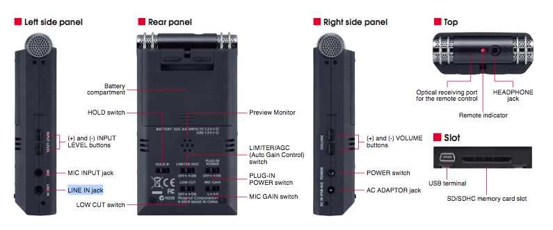 Quote:
Looking back at our conversations here, it looks like you point this out at least a couple times and I never put two and two together. For example: Quote:
I wonder if I hurt any of my equipment? I do have a tendency to learn the hard way. Quote:
Quote:
Thank you so much for teaching a noob like me the ropes!!!! Quote:
Quote:
Have a great day! Cheers, Micky
__________________
Home: See "Work" :) Work: Canon XH A1, CS3/CS4/CS5/Final Cut Studio/Final Cut Express/Premiere Elements |
|||||||
|
|
|
|
|
#55 | |
|
Trustee
Join Date: Jan 2011
Location: Pennsylvania
Posts: 1,796
|
Re: Binaural bass crackling: How to fix/avoid?
Quote:
If you won't buy that from a philosophical perspective, consider this. Suppose you had listened to your planetarium track and said to yourself, "Dang, I hope that doesn't happen next time." But you had not posted the question and the audio samples here. You (and we) would really have no idea what went wrong. Now imagine that next week you found yourself with a once-in-a-lifetime opportunity to record something irreplaceable. (The President and the Marine Band show up, unannounced, at the local high school, and you happen to be passing by.) So you hook up your gear the same way, make a recording, and end up with the same clicks. You'd be really discouraged, right? Instead, you now have some new data, you understand your equipment better, and in all likelihood your next recording will be much better. That's why I think any positive learning experience is a good one. Note that I did not smack your knuckles with an oak yardstick, so hopefully the experience was not too painful. ;) I am always happy to explain, whenever an explanation is requested. The only time I walk away is when the person on the "receiving" end of the lesson tries to argue with me, rather than being open to a learning experience. Clearly it's always a good idea to read, re-read, and thoroughly digest the manuals for all your equipment. Your case is a good example. Of course it's just "common sense" to connect the mics to the mic input. Nothing in the recorder manual specifically warns you to the contrary (although there are some rather obscure-looking numbers in the specs that might give you a hint... if you have enough experience to understand the specs). But over in the literature for the mic/battery combo is this little warning (IMHO it should be in bold type): when using the battery box, use the recorder's LINE input rather than the MIC input. On the other hand, if all this equipment and terminology is new to you, you might not even realize the significance of the term "Line input"... (you might just think that means "mic line" which is a commonly used phrase). My father was fond of saying, "We live and learn." (Also "You can't leave the table until you clean your plate.") When the learning process stops, we're in trouble. In your defense, I do not think those clicks are the result of clipping, nor are they a malfunction of the mics, nor are they a malfunction of the battery box. If they were clipping, all clipping would occur at a specific level; and the two channels would clip at different points in time. Also, your waveform does not look like clipping... is it not "flat-topped." So simply switching to the mic inputs might not correct the clicks that we've heard so far. Those clicks occur at the same time on both channels, and seem to occur right before I hear the AGC drop the level of the recorded signal. AGC should not produce clicks. Therefore, I really start to suspect some malfunction of the AGC (or limiter) in your recorder. That's why I want you to be sure to leave AGC and limiting off for your next test. Nevertheless, the mics should, in theory, be plugged into the line input, so I want you to do that, too. Just a little extra insurance. And besides, in some situation the mic inputs might clip (even if they haven't clipped so far)... so by using the Line inputs you will try to avoid that potential problem. So I think this has been a great experience. You've learned something about your mics, and something about your recorder (even if it might be bad news, you probably know how to avoid the problem in the future). You've learned how to calculate dB level differences, and you've learned how to fix a file with some very bizarre clicking noise. By the way, does Audacity have a Spectral view, so you can easily locate the clicks? And did you have a chance to try correcting any of them on your own? Carry on! |
|
|
|
|
|
|
#56 | |||||||||
|
Major Player
Join Date: Jul 2007
Location: Eugene, Oregon, USA
Posts: 213
|
Re: Binaural bass crackling: How to fix/avoid?
Quote:
Quote:
Thanks again for all of your help. :) Quote:
I actually run into those types of situations (well, not presidential encounters, but on a more micro local level) every once in a while via my job at the local newspaper... I can't even begin to count the number of times that I have gone out to film something, for example, and I come back with a huge list of "things I would do differently next time". :D Thanks to this forum, and the cool folks on here willing to help a noob (present company definitely included), every time I go out to film something my audio captures keep getting better and better! Quote:
I assumed that the battery pack just meant that I did not need to turn on the plugin power... I am not sure why I did not even consider the line input. :( Quote:
Random thought: I have never replaced the batteries in the battery pack. I don't think they are out of juice, but I am thinking that it might be a good idea to replace them for my next outing... Batteries are probably not related to the clicks, but it seems like it might be good to swap out batteries on a regular basis? Heck, I really wish my battery pack had some sort of battery level indicator. Quote:
Quote:
I will post some new recordings as soon as possible. Quote:
Quote:
Looking at Audicity, there is a "plot spectrum" in Analyze menu: 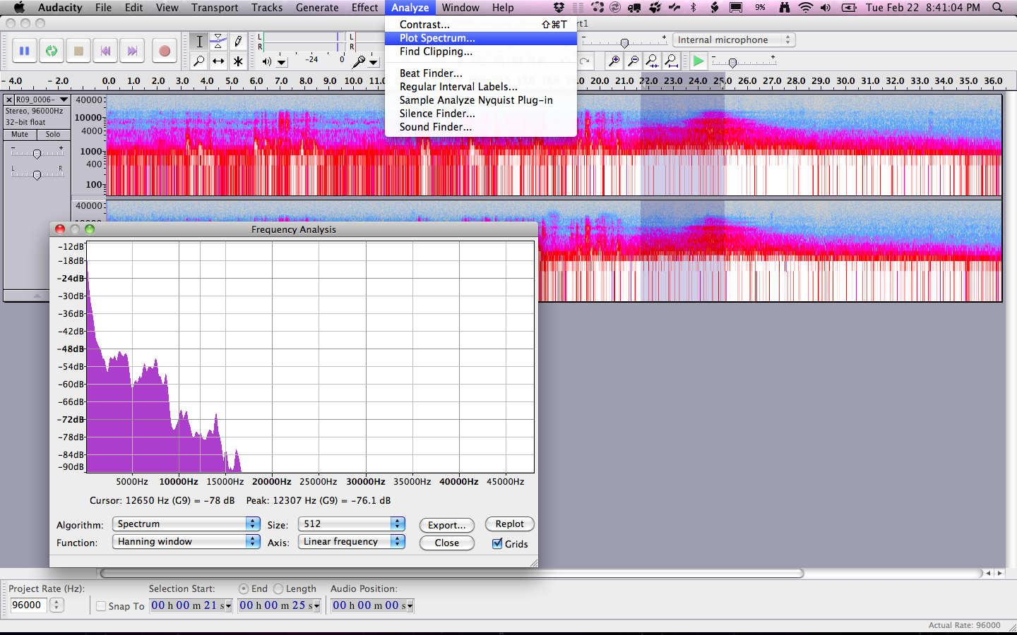 Gosh, I really wish I had CoolEdit Pro! I will experiment some more this weekend and get back to you with my findings. :) Thanks a billion Greg!!!!!! Have a great week! Chat with you this weekend. Cheers, Micky
__________________
Home: See "Work" :) Work: Canon XH A1, CS3/CS4/CS5/Final Cut Studio/Final Cut Express/Premiere Elements |
|||||||||
|
|
|
|
|
#57 |
|
Trustee
Join Date: Jan 2011
Location: Pennsylvania
Posts: 1,796
|
Re: Binaural bass crackling: How to fix/avoid?
Battery boxes first came into use with some of the MD recorders that didn't provide "plug in power" for electret mics. However, people realized that by using a rather high battery voltage (perhaps 9 volts), compared to the typical "plug in power" from a recorder (which is often in the 1.5 to 3 volt range), a battery box could also allow the mic to have more headroom before clipping. This is especially important when recording loud sounds: rock concert, construction site, etc.
The mic signal is proportional to the sound level. The battery box simply allows a higher level before the mic clips. So when you're recording something fairly loud, a typical mic input can't handle that high signal level from the mic (even 'though the audio signal voltage is lower than the 9 volt power supply). Thus you're safer to use the line input, especially when recording something loud. However... there's always a "however." In this case, if you are recording something fairly quiet, the line input might not have enough gain to get good recording levels, so you might need to use the mic input after all! -- Battery voltage goes down for two reasons: shelf life, and drain. Even if the batteries are never used they will slowly discharge. Packaging on batteries today (reputable brands, at least) includes an expiration date; that should be a safe indication of shelf life. When the battery box is not connected to anything, there should be no current drain. Even when recording, the drain should be fairly low. Hopefully the specs give you some idea of how many hours of use you can expect from a set of batteries. You don't really need a battery meter built into the battery box... that would just add to the size and price. You need an inexpensive digital multimeter. I have done some fairly precise electronic work from time to time, and I love good test equipment. I have Fluke meters and Tektronix oscilloscopes, etc. But you don't need anything fancy or pricey for your purposes. Inexpensive meters are amazingly good these days! I'm sure you can get one at the local Radio Shack, although from what I've seen of RS pricing lately, you will pay three times what it's really worth. In all honesty, something like this 7 Function Digital Multimeter will be adequate for checking battery voltage, and some other random electrical tasks. It will be slightly less accurate than a more expensive meter, but the difference won't really be significant for your application. It will be a lot less durable than a more expensive meter... the test leads will probably fail before anything else. But if you only use it once a month to check your battery box, and you don't abuse it, it will be OK. Eventually you'll want a better meter, but something like this is fine for a starter. Most non-rechargeable batteries should be a bit above 1.5 volts when they're fresh. Your meter should verify that. You probably want to discard them when they get down around 1.25 volts Again, read the literature that came with the battery box... if they specify some "discard" voltage other than my guesstimate of 1.25, follow their advice. If you're really OCD you could keep a chart of the voltage each time you check the batteries... personally, I wouldn't bother! |
|
|
|
|
|
#58 |
|
Major Player
Join Date: Jul 2007
Location: Eugene, Oregon, USA
Posts: 213
|
Re: Binaural bass crackling: How to fix/avoid?
Wow, I wish I knew half as much as you do when it comes to all of this stuff. Thanks Greg. You are a wealth of great information. :)
I hope that one of these days I can teach you something... If you ever need web design/coding help feel free to shoot me an e-mail. Also, thanks for link to that 7 Function Digital Multimeter! That looks like a fun device! Can't beat the $3.99 price tag. :) I will post my findings this weekend after I have played around more with Audacity. Thanks again!!! Have a great day! Cheers, Micky
__________________
Home: See "Work" :) Work: Canon XH A1, CS3/CS4/CS5/Final Cut Studio/Final Cut Express/Premiere Elements |
|
|
|
|
|
#59 | ||
|
Trustee
Join Date: Jan 2011
Location: Pennsylvania
Posts: 1,796
|
Re: Binaural bass crackling: How to fix/avoid?
Quote:
Quote:
Keep in mind that these meters have an internal battery (probably 9V) so when you see the little battery symbol on the meter's display, you'll need to replace that. Hey, I'm sorry, I've been extremely busy this week, I meant to post a screen grab of the spectral display from CoolEdit, so you know what you're looking for. I will try to get to it soon. |
||
|
|
|
|
|
#60 |
|
Trustee
Join Date: Jan 2011
Location: Pennsylvania
Posts: 1,796
|
Re: Binaural bass crackling: How to fix/avoid?
OK, Micky, here are a few screen captures to show how the Spectral View (in CoolEdit Pro) is used to find the clicks in your file. You already know how to fix them, once you find them.
The first image (Spectral-01.gif) shows what Spectral View looks like. You need to take a minute and get your head around this, because it's so different from waveform view. The horizontal axis is time scale, same as with Waveform view. Left channel is the upper graph, right channel the lower graph. However, the vertical axis is different. Look at the scale at the right side of the graph, you'll see that the vertical axis now represents frequency. Low frequencies at the bottom, high frequencies at the top. Intensity at any given frequency is indicated by color! For example, you'll see that there's a thin yellow-white area near the bottom of each channel's graph. The yellow-white color indicates that those are the loudest sounds. The fact that they're near the bottom of each graph indicates that they're lower frequencies (look at the scale, they're pretty much below 1,000 Hz.) Above the yellow, there's an area of red, which gradually tapers off to violet. Red is less loud than yellow, violet is less loud than red. That indicates that from about 1,000 Hz to about 5,000 Hz, there's still significant sound level, but it's gradually getting lower in amplitude. Above that, it tapers to darker violet and dark blue: the level is getting lower as the frequency gets higher. (That's what you'd expect in normal sound files.) Now look at those two big vertical spikes. The color of those indicates a sound that has a lot of energy up into the higher frequencies. The fact that it's a narrow spike indicates it's a pretty short duration in time. Those are the first pair of clicks in the "snippet" file that you sent. You'll notice that the spike on the right has a lighter blue background. That just indicates that I've selected (highlighted) that spike by dragging my mouse across it... the same as you'd select any area of any file. The second image (Spectral-02.gif) is the exact same part of the file, in time, but here we've switched back to the traditional Waveform View. Don't be confused by the file name... this is not a spectral view. You can see the same area, in time, is highlighted here. The third image (Spectral-03.gif) shows that I've zoomed in on the time (horizontal) scale, to the part of the file that I previously selected. I've also zoomed in slightly on the amplitude (vertical) scale. You can start to see the click clearly. The fourth image (Spectral-04) is zoomed in even further. Now you can see the click clearly. You recognize this from the images I sent with my click-fixing explanation last week. The point of this brief demo is to illustrate what the Spectral View looks like, and how you use it to accurately find each click in the file. Hopefully, Audacity has a similar spectral view, so you can easily find all the remaining clicks (in the file I fixed last week), and then try fixing them yourself. Make sense? It looks as if the spectral view in Audacity will let you see the same thing. I like CoolEdit's color scheme better than the Audacity color scheme in the image you posted... maybe because I'm used to looking at an oscilloscope which has a black screen except for where the beam traces the waveform. Maybe you can change the color scheme on Audacity so it's a bit clearer. Note, too, that my Spectral View has a linear frequency scale, so the fundamentals are all really squished down near the bottom. That makes it very easy to spot high frequency anomalies. Your spectral view has a logarithmic frequency scale, so the spikes (which show the clicks) don't stand out as well. Maybe you can change Audacity's spectral view to have a linear scale. Let me know how you make out... Carry on! P.S.: How did you get your thumbnails up in the body of the post? I added them as attachments and they all ended up at the bottom. |
|
|
|
| ||||||
|
||||||
|
|